Quantcast
Channel: AutoCAD Tips
Viewing all 89 articles
Browse latest View live

AutoCAD 2015 Resize Model Space Viewports

$
0
0

AutoCAD 2015 now makes resizing model space viewports intuitive and easy.

If you use multiple model space viewports, you’ll love this feature.

A special note needs to be made that the frame of the model space viewports has 2 areas. The area where the plus sign + resides is meant for adding a new viewport. The other area consists of the rest of the viewport edge and has the symbol with 2 lines.

Viewport frame picture 2

Resize a viewport by simply left-click and dragging the edge of the viewport within the “2 line” area.

The intersection of multiple viewports can be dragged to adjust the size all of the intersecting viewports.

Viewport Frame 1To add a new model space viewport, you can left-click and drag the plus sign + near the top or right side of the viewport edges.

You can also left-click and drag anywhere along the viewport edge and hold the Ctrl key to make a new viewport.

If you would like te delete a viewport, you can simply drag a viewport edge  until it collapses.

Viewport Frame 2


Viewport Frame picture 1


FLATSHOT In Action

$
0
0

We recently were given some 3D models by a subcontractor that needed to be incorporated into our drawings. There was one model in particular that was rather large in file size considering that it was only a small part of our overall design for the project. And to top it off, the 3D model from the subcontractor was to be placed about 11 times throughout the overall model. Even when the large file was brought into the drawing as an XREF, many of the AutoCAD designers experienced loading times of about 10 minutes.

The file size of the large model is almost 50 megabytes even after trying many methods to reduce its size. The method that we found that worked wonders was to use a FLATSHOT representation of the 3D model as a substitute for the 3D model.

Here’s how:

Below is a view of the piece of equipment that is 50 megabytes.

3D view of 50 megabyte file

3D view of 50 megabyte file

Below is a top view of the large file. This view is all that a majority of the designers needed to see in their drawings

Flatshot 2 Top View

The FLATSHOT command can be used at the command line or the tool can be found on the ribbon under the “3D Modeling” workspace under the “Home” tab > “Section” panel (dropdown) > “FLATSHOT

Note: that the view that is currently being shown on-screen will be used to produce the FLATSHOT version of the model. Think of this command as you orient your view of a 3D model and then take a picture with a camera. That picture is now the flattened 2d representation of the 3D model.
Keeping that in mind, if needed we could go to the side elevation views of the 3D model and produce FLATSHOT versions of those views so that they could be incorporated into someone’s drawing as well – thus reducing the time of opening the larger file.

Flatshot 3 Flatshot on ribbon


For this instance, I used the following settings to produce the FLATSHOT.

I suggest playing with the various settings to meet the needs of your particular project.

Flatshot  settings1

Once the FLATSHOT file is created it is a good idea to open the file and try to clean it up further. Some commands that might help are: OVERKILL, PURGE, JOIN, AUDIT

Below is a file size comparison of the large 3D model, the FLATSHOT version and the cleaned up FLATSHOT

Flatshot 4  File shize comparison

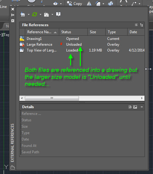
Now that we have a 2D version of the 3D model, the designers simply unload or detach the larger model from the XREF Manager in AutoCAD and load the FLATSHOT version.

Note: it is important to assign a person to take resposibility of keeping the 3D model and the FLATSHOT version in synch. If the 3D model was to be altered or moved in some way, the FLATSHOT would need to be updated so that everyone is using the most current data. In our instance at work, the large 3D model was not going to change through the project so it was an easy 1-time solution.


Flatshot 5 XREF manager unloaded


Fix Install or Uninstall Errors

$
0
0

Here is a possible fix for fixing errors that might have occurred during an install of AutoCAD (or any other program) that is preventing you from doing a “repair” or “Re-install.”

Scenario: An issue that has happened at work a few times recently was that a user updated to a new version of AutoCAD but for some reason it doesn’t open. I would then check to see if the files seemed to be copied correctly and tried to manually launch the acad.exe but that didn’t work either. I then went to the computer’s “Control Panel” to do a “Repair” or “Reinstall” of the new version of AutoCAD. The version of AutoCAD seems to be listed in the list of programs but once it is selected, the “Control Panel” says that it can’t be repaired because there was an error during installation.

Once these frustrating steps were tried over and over again, the common fix was to have the user’s machine re-imaged so that a fresh install could be applied. That is, until we found this useful link from Microsoft: http://support.microsoft.com/mats/Program_Install_and_Uninstall

It is a free utility from Microsoft that finds errors of an install that will hopefully allow the program to be successfully uninstalled and then re-installed.

I hope that this utility can help

~Greg

Microsoft Repair 1


AutoCAD 2015 Purge DGN Junk

$
0
0

That’s right, I called it “Junk”.

Recently we have been experiencing excessive bloating of files because somewhere in our project someone has either referenced in a drawing that was opened with Microstation or they have copied in something from a drawing that was used by Microstation.

Below is an example of a drawing that was almost 14 megabytes in size and needed to email it to someone out “in the field” but because of its file size, it was too large to email.
PURGE DGN 1


When you start the PURGE command in AutoCAD 2015, you now have the option to purge “Orphaned data.” AutoCAD apparently handles Microstation linestyles and text styles differently so the info that defines these objects becomes “orphaned” and can bloat drawings severely.

Check the box as shown below

PURGE DGN 2


If you have any of this purge-able data, the progress of the purge will be shown in the lower right of the AutoCAD screen (shown below)

PURGE DGN 3


To purge the “Orphaned” DGN junk from your drawings using the command line version of PURGE command in a script or macro, use the O (letter O) after issuing -PURGE from the command line.

PURGE DGN 4


Note: after purging what could be a lot of data from a drawing, it is a good idea to AUDIT your drawing. In the command line, enter AUDIT [enter] Y [enter]

For more info about how to purge unused DGN info from your drawings, check out these links:

Autodesk’s hotfix for AutoCAD 2013 & 2014: http://knowledge.autodesk.com/support/autocad/downloads/caas/downloads/content/autocad-C2-AE-dgn-hotfix.html

Kean’s explanations:

http://through-the-interface.typepad.com/through_the_interface/2012/12/purging-unwanted-dgn-linestyle-data-from-an-autocad-drawing-using-net.html

http://through-the-interface.typepad.com/through_the_interface/2013/07/autocad-dgn-hotfix-now-available.html


AutoLISP: ATTWIPE Clear Selected Attribute Values

$
0
0

Here is one that lets you easily clear the selected attribute tag(s).

This is especially helpful for when you are editing titleblocks that have populated attributes or when you copy a block (symbol) that already has attribute values already populated.

Here’s how:

(After loading of coarse)

  • ATTWIPE [enter]
  • Select the individual attributes that you would like to clear…
  • hit [enter] when finished to end the routine

ATTWIPE1


;; ------------------------------------------------------------------------------
;; AttWipe - © 2005 by Chuck Chauvin
;; Posted at: http://www.theswamp.org/index.php?topic=4934.0;all
;; Clears (wipes) the value of a selected attribute
;; ------------------------------------------------------------------------------
(defun C:AttWipe (/ AttSel AttLoc)
  
  (defun *error* (msg)
    (princ "\nInvalid selection.")
    (princ)
  );_ end defun *error*

  (defun SelectIt (msg)
  (setq AttLoc (cadr (setq AttSel (entsel (strcat "\nPick " msg " to wipe: ")))))
    );_ end defun SelectIt

  (defun WipeIt (/)
    (command "-attedit" "y" "" "" "" AttLoc "" "v" "r" "" "n")
    );_ end defun WipeIt

  (setvar "cmdecho" 0)
  
  (SelectIt "attribute")
  (WipeIt)
  (while AttSel
    (SelectIt "next attribute")
    (if	(= (type AttSel) 'list)
      (WipeIt)
      (setq AttSel nil)
      ) ;_ end if
    ) ;_ end while
  (princ)
  );_ end defun AttWipe
;; ------------------------------------------------------------------------------

AutoLISP: Updated Join Dimensions for AutoCAD 2014 & 2015

$
0
0

I was made aware that the Join Dimensions routine previously posted [here] wasn’t working for AutoCAD 2014 & 2015 so here is an updated version.

Here’s how:

  • After loading JDIMS [enter] to start
  • Select the first dimension
  • Select the second dimension

Note: the two dimesnions have to be the same type of dimension (either both Aligned or both Rotated…)

JDIMS for 2014 & 2015


;Shusei Hayashi
;OffshoreCad&Management Inc.
;10F Jaka Bldg., 6780 Ayala Ave.,
;Makati, Philippines
;http://www.offshorecad.com.ph/
;http://www.offshore-management.com.ph/
; Slightly modified to work with AutoCAD 2014 & 2015
; Greg Battin www.autocadtips.wordpress.com
; 

(defun c:JDIMS( /  Flag ObjName1 ObjName2 Ang Ang2 Pt1 Pt2 Pt3 Pt4)
	(princ "\n convert two dimensions to total Dimension on the same position")
	(princ "\n **********************************")
	(setq *error* *myerror*)   
	(SD1028)
	(setq LegLen 7.0)
	(setq Flag nil)
	(get_layer&ltype&color)
	(RegistryRead_1001)
	(setvar "Clayer" Lay1)
	(setvar "Cecolor" Col1)
	(setvar "Celtype" LT1)
	(while (= Flag nil)
	   (setq ObjName1 (car (entsel "\n Select 1st Dimension :")))
		(if (and ObjName1(= (cdr (assoc 0 (setq Data1 (entget ObjName1)))) "DIMENSION"))
			(setq Flag T)
		)
	)
	(redraw ObjName1 3)
	(setq theStyle (SD3511 3 ObjName1))
	(setq Flag nil)
	(while (= Flag nil)
		(setq ObjName2 (car (entsel "\n Select 2nd Dimension :")))
		(if 	(and 	ObjName2 
				(= (cdr (assoc 0 (setq Data2 (entget ObjName2)))) "DIMENSION")
				(or	(equal (abs (- (cdr (assoc 50 Data1))(cdr (assoc 50 Data2)))) 0.0 0.0001)
					(equal (abs (- (cdr (assoc 50 Data1))(cdr (assoc 50 Data2)))) pi 0.0001)
				)
			)
			(setq Flag T)
				(princ "\n two dimensions should have same angle")
		)
	)
	(redraw ObjName1 4)
	
	;
	(setq PList (list (cdr (assoc 13 Data1))(cdr (assoc 14 Data1))(cdr (assoc 13 Data2))(cdr (assoc 14 Data2))))
	;
	(setq PList2 (list (cdr (assoc 10 Data1)) (cdr (assoc 10 Data2))))
	;
	(if (/= (distance (cdr (assoc 14 Data1))(cdr (assoc 10 Data1))) 0)
		(setq Ang (angle (cdr (assoc 14 Data1))(cdr (assoc 10 Data1))))
		(setq Ang (+ (angle (cdr (assoc 13 Data1))(cdr (assoc 14 Data1))) (* 0.5 pi)))
	)
	
	(setq Ang2 (+ Ang (* -0.5 pi)))
	;ƒŒƒCƒ„[
	(setq ItsLayer (cdr (assoc 8 Data1)))
	
	;
	(setq PList_n (mapcar '(lambda(x)(SD1862 x Ang2))PList))
	(setq PList2_n (mapcar '(lambda(x)(SD1862 x Ang2))PList2))
	;
	(setq PList_n_x (mapcar 'car PList_n))
	;
	(setq PList2_n_y (mapcar 'cadr PList2_n))
	
	;
	(setq Position1 (vl-position (apply 'min PList_n_x) PList_n_x))
	
	(setq Position2 (vl-position (apply 'max PList_n_x) PList_n_x))
	;
	(setq Position3 (vl-position (apply 'max PList2_n_y) PList2_n_y))
	
	
	(setq Pt1 (nth Position1 PList))
;	(checkcircle Pt1 1.0 "A21")
	(setq Pt2 (nth Position2 PList))
;	(checkcircle Pt2 1.0 "A31")
	(setq Pt3 (nth Position3 PList2))
;	(checkcircle Pt3 1.0 "A51")
;	(setq Pt4 (polar Pt3 Ang (* LegLen Scale)))
;	(checkcircle Pt4 1.0 "A21")
	
	(setq 	Pt1 (trans Pt1 0 1)
			Pt2 (trans Pt2 0 1)
			Pt3 (trans Pt3 0 1)
;			Pt4 (trans Pt4 0 1)
	)
	(setq UAng (angle '(0 0) (getvar "UCSXDIR")))
	(setq Ang2 (- Ang2 UAng))
	(command "._dimstyle" "RE" theStyle)
	(command "dimrotated" (* 180 (/ Ang2 pi)) Pt1 Pt2 Pt3)
	(command "change" (entlast) "" "P" "LA" ItsLayer "")
	(entdel ObjName1)(entdel ObjName2)
 	
	(SD2056)
	(setq *error* nil)
	(princ)
)
;-----------------------------------------
(defun RegistryRead_1001()
	(setq Path1001 "HKEY_CURRENT_USER\\Software\\SpeedDraftLT\\SD_1001")
	(if (vl-registry-read Path1001 "LegLen" )
		(progn 	(set_tile "LegLen" (vl-registry-read Path1001 "LegLen"))
				(setq LegLen (atof (vl-registry-read Path1001 "LegLen")))
		)
		(setq LegLen 7.0)
	)
	(if (and (vl-registry-read Path1001 "Lay1" )(member (vl-registry-read Path1001 "Lay1") Laylist1))
		(progn 	(set_tile "Lay1" (itoa (vl-position (vl-registry-read Path1001 "Lay1") Laylist1)))
				(setq Lay1 (vl-registry-read Path1001 "Lay1"))
		)
		(progn 	(setq Lay1 (getvar "Clayer"))(set_tile "Lay1" (itoa (vl-position Lay1 Laylist1))))
	)
	(if (and (vl-registry-read Path1001 "LT1" )(member (vl-registry-read Path1001 "LT1") Laylist3))
		(progn 	(set_tile "LT1" (itoa (vl-position (vl-registry-read Path1001 "LT1") Laylist3)))
				(setq LT1 (vl-registry-read Path1001 "LT1"))
		)
		(progn 	(setq LT1 "ByLayer")(set_tile "LT1" "0"))
	)
	(if (and (vl-registry-read Path1001 "Col1" )(member (vl-registry-read Path1001 "Col1") Laylist2))
		(progn 	(set_tile "Col1" (itoa (vl-position (vl-registry-read Path1001 "Col1") Laylist2)))
				(setq Col1 (vl-registry-read Path1001 "Col1"))
		)
		(progn 	(setq Col1 "ByLayer")(set_tile "Col1" "0"))
	)
)
;----------------
(defun SD1028 ()
  (setq OldCmdEcho (getvar "CMDECHO"))
  (setvar "CMDECHO" 0)
  (command "undo" "be")
  (setq OldOsmode (getvar "OSMODE"))
  (setq OldLayer (getvar "CLAYER"))
  (setq OldLType (getvar "CeLType"))
  (setq OldCeLWeight (getvar "CeLWeight"))
  (setq OldColor (getvar "CeColor"))
  (setq OldOrtho (getvar "ORTHOMODE"))
  (setq OldDStyle  (getvar "DIMSTYLE"))
  (setq OldExpert (getvar "Expert"))
  (setvar "EXPERT" 0)
  (setq Path_Lang "HKEY_CURRENT_USER\\Software\\SpeedDraftLT")
;  (if (vl-registry-read Path_Lang "SD_Language" )
;  	(setq SD:Lang (vl-registry-read Path_Lang "SD_Language" ))
;  	(progn	(setq SD:Lang "J")
;  			(vl-registry-write Path_Lang "SD_Language" "J")
;  	)
;  )
  (princ)
)
;********************************
(defun SD2056 ()
  (setvar "OSMODE" OldOsmode)
  (command "undo" "end")
  (setvar "CLAYER" OldLayer)
  (setvar "CeLType" OldLType)
  (setvar "CeLWeight" OldCeLWeight)
  (setvar "CeColor" OldColor)
  (setvar "ORTHOMODE" OldOrtho)
  (setvar "Expert" OldExpert)
  (if (and (/= (getvar "DIMSTYLE") OldDStyle)(tblsearch "DIMSTYLE" OldDStyle))
  	(command "-dimstyle" "Restore" OldDStyle)
  )
  (princ "\n (C)OffshoreCad&Management")
  (setvar "CMDECHO" OldCmdEcho)
  (princ)
)

;********************************
(defun get_layer&ltype&color()
	(setq 	Lay (tblnext "LAYER" T)
			LT (tblnext "LTYPE" T)
			Laylist1 (list)
			Laylist2 (list "ByLayer" "Red" "Yellow" "Green" "Cyan" "Blue" "Magenta" "B/W")
			Laylist3 (list"ByLayer")
	)
	(While Lay
		(setq lay1 (list (cdr (assoc 2 Lay)))
			  lay2 (cdr (assoc 62 Lay))
			  lay3 (list (cdr (assoc 6 Lay)))
			  Laylist1 (append Laylist1 lay1)
			  Laylist3 (append Laylist3 lay3)
			  Lay (tblnext "LAYER")
		 )
	  	(if (> lay2 7)(setq  lay2 (list (itoa lay2)) Laylist2 (append Laylist2 lay2)))
	)
	(While LT
		(setq lay3 (list (cdr (assoc 2 LT)))
			  Laylist3 (append Laylist3 lay3)
			  LT (tblnext "LTYPE")
		 )
	)
	(setq 	Laylist1 (RemoveOverlap Laylist1)
			Laylist2 (RemoveOverlap Laylist2)
			Laylist3 (RemoveOverlap Laylist3))
)
;************************
(defun RemoveOverlap (	List2	/	List1	)
	(while List2
		(setq List1 (append List1 (list (car List2))))
		(setq List2 (vl-remove (car List2) List2))
	)
	List1
)
;;;---------Rotate----------------------------

(defun SD8446 ( PointA PointB Ang / XA YA XB YB PointC)

	(setq 	XA2(- (car PointA) (car PointB))
			YA2(- (cadr PointA) (cadr PointB))
	)
	(setq PointC (list (- (* XA2 (cos Ang))(* YA2 (sin Ang))) (+ (* XA2 (sin Ang))(* YA2 (cos Ang)))))
	(setq PointC (mapcar '+ PointC PointB))
	PointC
)
;****************************************************
(defun SD1862 (OldPt Ang / NewCs)
	(setq NewCs (SD8446 '(1 0) '(0 0) Ang))
	(setq NewPt (trans OldPt 0 NewCs))
	(setq NewPt (list (nth 2 NewPt)(nth 0 NewPt)))
	NewPt
)
;**********************
(defun SD3511 (g e)
	(cond
		((= (type e) 'ename) (cdr (assoc g (entget e))))
		((= (type e) 'list) (cdr (assoc g e)))
	)
)
;********************************
(defun *myerror* (msg)
	(setq *error* nil)
	(SD2056)
	(princ "\n Error in SpeedDraftLT")
	(princ)
)
	(princ "\n Command Name: JDIMS")
(princ)

Helpful Settings for Plotting 3D Solids in AutoCAD

$
0
0

This post isn’t a fix-all solution but it has helped printing/plotting issues that I’ve recently encountered. There are some helpful AutoCAD variables and an adjustment to your preferred “Visual style(s)” that can help make printing 3D solids look correct in your print.

First – The issue that we encountered was that intersecting solids didn’t have a clear intersection in the print and curved 3D objects were displaying lines where a “tessellation” of the curves would be.

print Settings for Solids 1a

The settings of the visual styles for a viewport can be confusing. Note that there is a difference of a “Visual Style” and “Shade Plot” setting. This trips me up a lot and I confuse them for each other…

For the purposes of this blog post, I will keep it simple and keep the visual style of the Viewport set to “2D Wireframe” (shown below)

Print Settings for solids 2 1a

  • Then change the “Shade Plot” setting of the viewport by selecting the edge of the viewport from paper space and opening the “Properties” palette. (right-click > Properties)
  • Change “Shade Plot” from “As Displayed” to “Hidden”

Print Settings for Solids 2 a

Change the Visual Style to not display the “Isolines”
Use the command VISUALSTYLES in the command line to open the Visual Styles palette.

  1. Select the Visual Style that you wish to change in the upper section of the palette. In this example, I changed the “Hidden” Visual Style.
  2. Scroll down in the palette to the “Edge Settings” section, Change the property called “Show” from “Facet Edges” to “Isolines
  3. Change the “Number of Lines” setting from “20” to “0” (zero).

Print Settings for Solids 2 b


In addition to making this change to the Vistual Style, changing the following AutoCAD variables helps the plot to display correctly.

Print Settings for Solids 3


The result is shown below. Hopefully you find this useful.

Print Settings for Solids 4


AutoLISP: Polyline Direction preview

$
0
0

The simplicity of this routine is why I like it so much. You simply run the command and then select a polyline and it displays temporary arrows that show the direction of the polyline. Once you either zoom in or out, or even use RE [enter] for a REGEN, the temporary arrows will stop displaying.

All credit goes to Luis Esquival and RonJon from the.swamp.org for sharing and editing this routine.

Below – Various polylines have their directions shown

PolyLine Direction

As an extra bonus, this routine works on 3DPOLYLINEs. Even though the arrows aren’t exactly aligned, it is still nice to have a way to show the direction…

PolyLine Direction 3DPOLY

~enjoy


;; Original Code by Luis Esquival http://www.theswamp.org/index.php?topic=9441.msg169894#msg169894
;; Displays the direction of polylines with temporary arrows
;;
;; Modified by RonJonP
;; http://www.theswamp.org/index.php?topic=35706.msg409414#msg409414
(vl-load-com)
(defun getarcsegment (cen r fromvertex p2 / a1 a2 d)
  (if (and fromvertex p2)
    (progn (setq a1 (angle cen fromvertex)
		 a2 (angle cen p2)
	   )
	   (if (or (< a1 a2) (equal a1 a2 0.001))
	     (setq d (* r (- a2 a1)))
	     (setq d (* r (- (+ 6.2831853 a2) a1)))
	   )
    )
    ;; is a circle
    (setq d (* r 6.2831853))
  )
)

(defun getbulgedata (bulge fromvertex p2 / dir theta beta radio dat)
  (setq	dir   (cond ((minusp bulge) -1.0)
		    (t 1.0)
	      )
	theta (* 4.0 (atan (abs bulge)))
  )
  (if (> theta pi)
    (setq theta	(- (* 2.0 pi) theta)
	  dir	(* -1.0 dir)
    )
  )
  (setq	theta (/ theta 2.0)
	radio (abs (/ (distance fromvertex p2) (* 2.0 (abs (sin theta)))))
	beta  (+ (angle fromvertex p2) (* (- (/ pi 2.0) theta) dir))
	pc    (polar fromvertex beta radio)
  )
  (getarcsegment pc radio p2 fromvertex)
)

(defun getlwpolydata
       (vla_poly / name endparam param closed fromvertex p2 midp bulge vlist)
  (setq closed (vla-get-closed vla_poly))
  (setq endparam (vlax-curve-getendparam vla_poly))
  (setq param endparam)
  (setq i 0)
  (while (> param 0)
    (setq param (1- param))
    (setq fromvertex (vlax-curve-getpointatparam vla_poly i))
    (if	(vlax-property-available-p vla_poly 'bulge)
      (setq bulge (vla-getbulge vla_poly (fix i)))
    )
    (setq nextvertex (vlax-curve-getpointatparam vla_poly (+ i 1)))
    (setq dis (distance fromvertex nextvertex))
    (setq midpt (vlax-curve-getpointatparam vla_poly (+ i 0.5)))
    (if	(and bulge (not (zerop bulge)))
      (progn (setq bulge (getbulgedata bulge fromvertex nextvertex))
	     (setq etype "ARC")
      )
      (progn bulge (setq etype "LINE"))
    )
;;;;;;    (if	(not :rcmPrefixArcText)
;;;;;;      (setq :rcmPrefixArcText "L="))
    (setq vlist	(cons (list ;; vertex number
			    (+ i 1)
			    ;; object type
			    etype
			    ;; midpoint
			    midpt
			    ;; start vertex
			    fromvertex
			    ;; ending vertex
			    nextvertex
			    ;; curved or straight length
;;;;;;	       (if (= eType "ARC")
;;;;;;		 (strcat
;;;;;;		   :rcmPrefixArcText
;;;;;;		   (rtos bulge (rcmd-getUnits-mode) :rcmPrec))
;;;;;;		 ;; is straight
;;;;;;		 (rtos dis (rcmd-getUnits-mode) :rcmPrec))
		      )
		      vlist
		)
    )
    (setq i (1+ i))
  )
  (reverse vlist)
)

(defun dib_flechdir (lst_dat / unidad angf dirf pfm pf1 pf2 pf3 pf4 pftemp)
  ;; set arrow length according to screen height
  ;; to draw the same arrows at any level of zoom
  (setq unidad (/ (getvar "VIEWSIZE") 15))
  (foreach dat lst_dat
    (setq angf (cadr dat)
	  dirf (caddr dat)
	  pfm  (polar (car dat) (+ angf (/ pi 2)) (* unidad 0.3))
	  pf1  (polar pfm (- angf pi) (/ unidad 2.0))
	  pf2  (polar pfm angf (/ unidad 2.0))
    )
    (if	(= dirf 1)
      (setq pf3	(polar pf2 (- angf (/ (* pi 5.0) 6.0)) (/ unidad 4.0))
	    pf4	(polar pf2 (+ angf (/ (* pi 5.0) 6.0)) (/ unidad 4.0))
      )
      (setq pftemp pf1
	    pf1	   pf2
	    pf2	   pftemp
	    pf3	   (polar pf2 (+ angf (/ pi 6.0)) (/ unidad 4.0))
	    pf4	   (polar pf2 (- angf (/ pi 6.0)) (/ unidad 4.0))
      )
    )
    (if	flag_dir
      (progn ;; draw green arrow
	     ;; when you are changing direction
	     (grdraw pf1 pf2 3)
	     (grdraw pf2 pf3 3)
	     (grdraw pf2 pf4 3)
      )
      (progn ;; draw arrow
	     (grdraw pf1 pf2 4)
	     (grdraw pf2 pf3 4)
	     (grdraw pf2 pf4 4)
      )
    )
  )
  (setq flag_dir nil)
)

;;; Command for test...
(defun c:PLD (/ pol obj pol_data)
  (setq	pol	 (car (entsel "\nSelect polyline: "))
	obj	 (vlax-ename->vla-object pol)
	pol_data (getlwpolydata obj)
  )
  (dib_flechdir
    (setq lst_dat
	   (vl-remove
	     nil
	     (mapcar (function (lambda (i)
				 (if (nth 2 i)
				   (list (nth 2 i) (angle (nth 3 i) (nth 4 i)) 1)
				 )
			       )
		     )
		     pol_data
	     )
	   )
    )
  )
  (princ)
)


Reverse Polyline Moves Origin

$
0
0

Today’s tip is more of a “head’s up” to be aware of when using the REVERSE command on a closed polyline.

The Reverse command will reverse the direction of selected objects. What is reversed is the direction or the order of the way that the objects were drawn.

You can use the command REVERSE to launch this command or it is located on the ribbon on the Home tab > Modify Panel > Reverse (shown below)

Reverse Command on Ribbon


You can find the “origin” of a polyline by selecting the polyline, then right-click and select “Properties” to open the properties palette.

Click inside “Current Vertex” section of the palette. The first vertex will have a temporary marker “X” on-screen at the “origin.”

Polyline Vertex Reverse 1


When you click on the up or down arrows of the “Current Vertex” section, you will see the direction of the polyline. clicking the Up arrows will show the direction in which the polyline was created. Clicking down will go backwards…

Polyline Vertex 3 initial direction


when using the Reverse command so that the direction is changed, note that the origin changes on closed polylines. This may not be a big deal for most situations but there are instances when each vertex is included in a report and its coordinates are included in the report. And maybe the person who drew the polyline drew the polyline in the wrong direction. Hopefully, this can be corrected by using the REVERSE command.

Below is the polyline as shown above and its origin after the reverse command is used on it. Notice that the origin changes.

Polyline Vertex Reverse 2


Polyline Vertex 4 After REVERSE command


AutoLISP: ReOrder Polyline Origin

$
0
0

Taking into consideration the previous posts about determining the origin of a closed polyline, Finding the direction of a polyline and being aware that the REVERSE command will change the origin of a closed polyline – the LISP file in this post will help you have control of defining the “Origin” or first vertex of a polyline. And as a bonus, it even works on 3D Polylines.

Here’s how:

  • Load the lisp file
  • REORDERPOLY [enter]
  • Select the polyline
  • Click an endpoint to define the new origin

ReOrder Polyline Origin


3D Polyline shown below


ReOrderPoly 3D Poly


;;; T Willey
;;; Re Order Polyline Origin
;;; http://www.theswamp.org/index.php?topic=12624.msg154976#msg154976
(defun c:ReOrderPoly (/ Sel Pt Pobj EntData Ptype PtList VertexPt PtListIndex StWd EndWd PolyList OldIndex StPos cnt
                        tmpList ShouldClose)

(vl-load-com)
(defun ChangeOldStyle (Ent Pt / Pent cnt EntData PolyInfoList StPos StPt ShouldClose)

(setq Pent Ent)
(setq cnt 0)
(while
 (and
  (setq Ent (entnext Ent))
  (setq EntData (entget Ent))
  (= (cdr (assoc 0 EntData)) "VERTEX")
 )
 (setq PolyInfoList
  (cons
   (list
    cnt
    (cdr (assoc 10 EntData))
    (cdr (assoc 42 EntData))
    (cdr (assoc 40 EntData))
    (cdr (assoc 41 EntData))
   )
   PolyInfoList
  )
 )
 (if (equal cnt 0)
  (setq StPt (cdr (assoc 10 EntData)))
 )
 (setq cnt (1+ cnt))
 (setq ShouldClose (equal StPt (cdr (assoc 10 EntData)) 0.0001))
)
(foreach Lst PolyInfoList
 (if (equal Pt (cadr Lst))
  (setq OldIndex (car Lst))
 )
)
(setq PolyInfoList (reverse PolyInfoList))
(setq StPos (vl-position (assoc OldIndex PolyInfoList) PolyInfoList))
(setq cnt StPos)
(setq Ent Pent)
(while
 (and
  (setq Ent (entnext Ent))
  (setq EntData (entget Ent))
  (= (cdr (assoc 0 EntData)) "VERTEX")
 )
 (setq EntData (subst (cons 10 (cadr (nth cnt PolyInfoList))) (assoc 10 EntData) EntData))
 (setq EntData (subst (cons 42 (caddr (nth cnt PolyInfoList))) (assoc 42 EntData) EntData))
 (setq EntData (subst (cons 40 (cadddr (nth cnt PolyInfoList))) (assoc 40 EntData) EntData))
 (setq EntData (subst (cons 41 (last (nth cnt PolyInfoList))) (assoc 41 EntData) EntData))
 (entmod EntData)
 (setq cnt (1+ cnt))
 (if (> cnt (1- (length PolyInfoList)))
  (setq cnt 0)
 )
)
(if ShouldClose
 (progn
  (setq EntData (entget Pent))
  (entmod (subst '(70 . 1) (assoc 70 EntData) EntData))
 )
)
(entupd Pent)
)
;-----------------------------------------------------------
(command "_.undo" "_end")
(command "_.undo" "_group")
(if
 (and
  (setq Sel (entsel "\n Select polyline: "))
  (setq Pt (getpoint "\n Select new starting point: "))
  (setq Pobj (vlax-ename->vla-object (car Sel)))
  (setq EntData (entget (car Sel)))
  (wcmatch (setq Ptype (cdr (assoc 0 EntData))) "*POLYLINE")
 )
 (if (= Ptype "POLYLINE")
  (ChangeOldStyle (car Sel) Pt)
  (progn
   (setq PtList (vlax-get Pobj 'Coordinates))
   (if
    (and
     (= (vla-get-Closed Pobj) :vlax-false)
     (equal (car PtList) (nth (- (length PtList) 2) PtList) 0.0001)
     (equal (cadr PtList) (last PtList) 0.0001)
    )
    (setq ShouldClose T)
   )
   (setq VertexPt 0)
   (setq PtListIndex 0)
   (repeat (/ (length PtList) 2)
    (vla-GetWidth Pobj VerTexPt 'StWd 'EndWd)
    (setq PolyList
     (cons
      (list
       VertexPt
       (list
        (nth PtListIndex PtList)
        (nth (1+ PtListIndex) PtList)
       )
       (vla-GetBulge Pobj VertexPt)
       StWd
       EndWd
      )
      PolyList
     )
    )
    (setq VertexPt (1+ VertexPt))
    (setq PtListIndex (+ 2 PtListIndex))
   )
   (foreach Lst PolyList
    (if (equal (list (car Pt) (cadr Pt)) (cadr Lst))
     (setq OldIndex (car Lst))
    )
   )
   (setq VertexPt 0)
   (setq PtList nil)
   (setq PolyList (reverse PolyList))
   (setq StPos (vl-position (assoc OldIndex PolyList) PolyList))
   (setq cnt StPos)
   (repeat (length PolyList)
    (setq tmpList (nth cnt PolyList))
    (setq PtList (append PtList (cadr tmpList)))
    (vla-SetBulge Pobj VertexPt (caddr tmpList))
    (vla-SetWidth Pobj VertexPt (cadddr tmpList) (last tmpList))
    (setq VertexPt (1+ VertexPt))
    (setq cnt (1+ cnt))
    (if (> cnt (1- (length PolyList)))
     (setq cnt 0)
    )
   )
   (vlax-put Pobj 'Coordinates PtList)
   (if ShouldClose
    (vla-put-Closed Pobj :vlax-true)
   )
  )
 )
)
(command "_.undo" "_end")
(princ)
)

[\code]


Changing A Block Insertion Point

$
0
0

You may come across blocks in a drawing where either the insertion point of the block doesn’t meet your needs. Hopefully this post will help you save some time editing your block and also there’s an added bonus, I will show you how to add extra insertion points to your block – Yes, you can have multiple…

In the picture below, the scenario is that I have multiple instances of a block that contains attributes and the insertion point for this block is located at an odd location.

Block Insertion Points 1


Without exploding the block and then recreating it, I suggest using the “Block Editor”

You can use the BEDIT command ( or command alias BE )and select the block from the list. Or an easier way is to:

  • Simply select an instance of the block that you would like to edit
  • Right click
  • Select “Block Editor”

Block Insertion Points 2


As you can see, the “Block Editor” option is greyed out which means that I am unable to use the block editor. And as shown below, when I use the BEDIT command, the command line says that the “Block Editor is disabled.”

Block Insertion Points 3


This okay, there is an AutoCAD system variable (setvar) that many CAD managers set that prevents users from editing blocks.

The AutoCAD system variable is BLOCKEDITLOCK (shown below) and has a very simple On & Off setting

Block Insertion Points 4


As shown below, simply enter BLOCKEDITLOCK in the command line and set it to 0 (zero) to allow the block editor to be used.

Block Insertion Points 5

  • You can now select your block and right click and select “Block Editor.”

Your block will now open in the magical world of the block editor.
Notice that the background color is different (grey) which is good so that you remember that you are in the block editor and not in a drawing space (model or paper).
Also note that the current ribbon tab is a “contextual tab” called “Block Editor” and the tools in this tab are helpful for editing blocks and that there is a palette called the “Block Authoring Palette”

One important thing to notice is that when you want to exit the block editor, the furthest right button on the tab labeled “Close Block Editor” is what you want to use.

Block Insertion Points 6


Selecting all of the objects in the block editor, I will now move them using the MOVE command to orient the desired “main” insertion point to 0,0 (shown below)

Block Insertion Points 7


If moving the insertion point is all that you need done to a block, you can now use the “Close Block Editor” button and click “Save changes…” so that the block will reflect the moved insertion point.

To add another (or multiple) insertion point(s) to the block:

  • Click on the “Parameters” tab of the palette
  • Click “Point” from the palette
  • Click to place the new point
  • Move the cursor away from the point you just picked, and place the “Parameter”
    (Note: usually when you place something from the “Parameters” tab, you need to also apply an action to that “parameter.” This is usually how you make a dynamic block. but placing these extra points alone, requires no other “actions” to be applied to make it “dynamic” for our purpose)

Block Insertion Points 8


  • Click “Close Block Editor
  • Click “Save the changes to (your block name)

Block Insertion Points 9Because our block has attributes, you might notice that the attributes didn’t move. This is because when the block was created, the “Lock Position” option was set to “Yes” when the Attribute was created.

Block Insertion Points 10


To fix this, Use the ATTSYNC command which can be found on the “Insert” tab of the ribbon > “Block Definition” panel drop down > Click on “Synchronize

  • Select the block that needs to be “synced”
  • Verify that you would like to sync the block by selecting Yes

Block Insertion Points 11


Now that the block is ready for use, you can make use of those extra insertion points by using the INSERT command (or command alias I )

  • Select the name of the block from the list to insert
  • Prior to placing the block, use the CTRL key to toggle through the various insertion points.

Block Insertion Points 12


Creating A Data Link With An Excel Table

$
0
0

Linking an Excel spread sheet to an AutoCAD drawing and displaying the excel table as an AutoCAD  “Table” is very helpful depending on how you “link” the Excel file to the AutoCAD table.

In this post, I describe how to make an AutoCAD “Data Link” first, and then inserting a table using this Data Link.

I have seen a few examples where using other methods have cause issues. So after testing various ways, I think that this method is a solid method.

In this scenario, we have engineers who need to update a drawing list that happens to be an excel file (.xlsx) and they would like to link this to AutoCAD so that when they make changes to the table, those changes are included in the AutoCAD file.

client_net

First we need to make a “Data Link”

Click the “Data Link” button on the “Linking & Extraction” panel of the “Insert” tab of the ribbon.

Data Link 1

  • When the “Data Link Manager” opens, click “Create a new Excel Data Link
  • Give the Data Link a unique name
  • Then click OK

Data Link 2


  • Now link the “Data Link” to an excel file by clicking the ellipsis button ( 3 dot button)
  • Navigate to the Excel file and select it
  • Then click “Open

Data Link 3


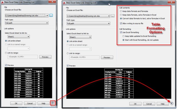
The dialog box called ” New Excel Data Link” will display and an additional preview is now shown in the bottom portion.

One very important thing to note about this Dialog Box is to expand it by clicking the right arrow. This allows for additional formatting options for the AutoCAD Table.

Data Link 4


Now you will insert an AutoCAD Table (shown below)

When the “Insert Table” dialog box displays, click “From a data link

Select the Data Link that you named earlier from the drop down list

Then click OK

Data Link 5


Place the table in the drawing

After the table has been placed, you should be good to go.

Lets say that an engineer updates the Excel spreadsheet. You will either get the below notification when the person has saved and checked in the file or the next time you open the drawing.

Data Link Update


The AutoCAD table will not update by itself, you will need to update it manually.

To do this:

  • Place the cursor in a cell of the table
  • Click the “Download from Source” button in the ribbon

Data Link 6


There are many other options available while placing a Data-Linked table so please look further in to this topic to meet your needs. This is a high-level look at adding a data link table to a drawing.

~enjoy


AutoCAD List of Command Aliases and Shortcut Keys

$
0
0

Today’s tip is simply a link to an excellent AutoCAD alias and shortcut reference guide provided by Autodesk & The AutoCAD team.

The link is found here: http://www.autodesk.com/store/autocad/autocad-shortcuts

I highly recommend learning command aliases like using XR in the command line instead of XREF or W instead of WBLOCK.

Note: There are many other useful examples in the linked resource. So don’t get overwhelmed or try to memorize all of them. If I could make a suggestion, skim the list of aliases or hot keys for the commands or tools that you use the most in your daily drafting routines and make a note of a few of them and try to utilize a couple one day at a time.

One more thing to note is that these are the default (out of the box) shortcuts and command aliases. Once you are comfortable with some of these default shortcuts you might realize that there are some default aliases that since they are assigned to an existing command. Luckily you can easily create brand new aliases and assign them to a command or you can assign an unused alias to a command.

A couple of examples of custom aliases that I use are CC = COPY, RR = ROTATE, SS = SELECTSIMILAR.

These aliases can be edited in the “Alias Editor” which appends the acad.pgp file.

For more help in running the ALIASEDIT command, refer to this previous post: http://autocadtips.wordpress.com/2010/11/06/system-variables-dialog-box/

ALIAS EDIT 1


Thank you to the AutoCAD team for making this list of shortcuts & aliases available in such an easy and thorough format.

~Greg


Turn On CADWorx Ribbon Tabs and Menu Bar

$
0
0

If you have lost your CADWorx Ribbon tabs or Menus (from the menu bar) you can simply load them by using the following in the command line:

LOADMENUPLANT [enter]

CADWorx ribbon tabs and menu

CADWorx 2013 and AutoCAD 2013 are shown in the above pic

For loading the CADWorx Equipment palette or toolbars see the following post: http://autocadtips.wordpress.com/2013/06/21/cadworx-equipment-palette/

A friend of mine also has a great blog post explaining how to load both the CADWorx Plant and Equipment modules in the same session found here: http://streamlined-design.blogspot.com/2013/07/use-acadrx-to-load-cadworx-plant-and.html

Please keep the Streamlined Design blog in mind for some terrific advanced AutoCAD customization tips & techniques for CAD managers and CAD admins. There are also some .NET programming examples available

~Greg


BASE Command – BEWARE of XREFs & Blocks

$
0
0

A perplexing issue crept its way into a project recently that revolves around the AutoCAD command BASE [enter].

This command can be found on the “Home” tab > Block panel (drop down – lower portion) “Base

Base 1

It can also be found on the “Insert” tab > “Block Definition” panel (drop down – lower portion) > “Set Base Point” button

Base 1-2


Note the description of the command as it is hovered over in the tool tip. It sounds like a description but it should also be a WARNING.

When you run the BASE command in a drawing note that the coordinates should be o,o,o (zero,zero,zero) [shown below].

Base 2

If the BASE command is run and these coordinates have been changed, notice the warning that appears (shown below). It seems to be more concerned about the Z coordinate not being set to zero than anything, but at least it lets you know that this has been changed.

Base 3


Using the BASE command can be useful for when you have a series of blocks that are in a folder and each drawing is an individual blocks. If for some reason, a block needs to have its insertion point moved, it might be easier to open the drawing and run the BASE command and then simply snap to a point to define the new “BASE” point, then trying to select all of the objects that make up the block and then move them to the coordinates (0,0,0).

But if you have dynamic blocks or properties of a block that require it to be opened and edited in the “Block Editor,” you are out of luck. The below warning will appear telling you that the BASE command will not work in the Block Editor.

Base5


Now here is the important thing to remember or at least try if you have a problematic drawing/model. Here is the scenario – An Electrical designer had a 3d model referencing all of the other disciplines (Piping, Structural, Civil, & Mechanical) and when he had his drawing opened, everything looked correct. But when every other discipline opened their model, everything was fine EXCEPT the electrical model. This is because somewhere along the process, the BASE command was used and was snapped to some random object. And as the description says, this will be the “Origin” or Base Point that other drawings will process and use when this drawing is inserted as a block or XREFed into their drawings.

Luckily, if the BASE has been changed, you can later use the BASE command and it will show the new coordinates – meaning it will not show (0,0,0) allowing you to easily enter these values thus fixing the XREF issue.


Issues With Using DEFPOINTS for Viewports

$
0
0

It may seem like a great idea to use the layer “DEFPOINTS” as the layer for your viewports since it doesn’t plot by default. And you may have heard from various posts that you shouldn’t do so but may have not understood why…

Here’s why:

It has to do with both Layer 0 (zero) and Defpoints.

Note: I am using “Layer 0 (zero)” because I dont want the zero to be confused as the capital letter O.

Layer zero is reserved for objects like blocks so if they are set to layer zero and you insert them into a drawing, the current layer could be set to anything, and that block will now be on that layer. So CAD managers might have Layer 0 (zero) turned off or even frozen so that people don’t use this layer to draw objects that should be on a designated layer.

If layer 0 (zero) is not turned off or frozen, you can select everything as normal (shown below

1 All Layers Selectable

Let’s say that you Freeze Layer 0 (zero) [shown below]

2 Freeze Layer Zero

Now try to select the same layers that were select-able prior to Layer 0 (zero) being frozen. You will notice that you cant select the objects that are on the DEFPOINTS layer. It’s like some sort of force field has been applied to these objects…

3 Try to select Objects on Defpoints


So how will this cause issues?
If your viewports are on the DEFPOINTS layer, and you want to later come and change the scale of the viewport, you will not be able to select the viewport. However, you can still double click inside the viewport to adjust the scale but some people use DEFPOINTS for placing other objects that they don’t want to plot like text that serve as notes or whatever. If they later what to erase them or move them or edit them, they wont be able to do so.

4 Example of viewport on DEFPOINTS


Don’t Forget that CADWorx P&ID Cfm.shx file

$
0
0

This issue comes up rather often when dealing with projects that use CADWorx. Some users use CADWorx and other people in the same project don’t. Perhaps they want to simply open a P&ID drawing (or other drawing that uses this file for linetypes) with just “vanilla” AutoCAD and upon opening the drawing they are greeted with the ever-annoying prompt that says: “One or more SHX files are missing. What do you want to do?”

Cfm shape file 1A

If you don’t have CADWorx installed on your machine, simply ignore this so that you don’t alter the drawing and how it is supposed to look/display. Then go find someone who does have CADWorx and ask if you can copy the “compiled shape file” (That is what an .shx file is…) and copy it to you your AutoCAD support path.

Most likely the culprit is the .shx file called “Cfm.shx” and it is located in the default CADWorx support path on your C: drive as shown below.

In the example below, I am using AutoCAD 2013 with CADWorx P&ID 2013. Your versions will vary but the file name of “Cfm.shx” remains the same. Also not that when you browse to your AutoCAD support path, it will not be the same as mine after the “Users” portion…

Cfm shape file 2

Shown below are some of the linetypes that use this .shx file that are unique and therefore, you can see why you wouldn’t want to simply replace the linetype upon opening…

Cfm shape file 1

Cfm Shape File 3


AutoLISP: EXTRIM Between Two Edges

$
0
0

The LISP routine featured today is by Marko Ribar and can be found at CADTutor.net at the following Link: http://www.cadtutor.net/forum/showthread.php?88293-EXTRIM-Between-Two-Lines&p=605998&viewfull=1#post605998 If you have any questions or requests or even saying a “Thank you” to Marko, about the routine, please post them at the forum. I am sure that Marko would like to know if he needs to tweak anything and would appreciate any gratitude.

Please copy the code from the CADTutor link above

The routine uses the concept of the EXTRIM command that is found in the Express Tools and applies this approach to trimming objects that cross both of the selected edges (boundaries).

Here’s how:

  • EXB2C [enter]
  • Select 2 separate objects to define the trimming edges
  • Click the cursor between the 2 edges that you selected to define the area that you want trimmed.

EXB2C 3 EXTRIM


Note that if objects do not cross both of the edges that you select, the outcome seems to not want to trim certain objects (shown below).

EXB2C 2

But if this is the scenario that you encountering, you should just use the Express Tool EXTRIM to accomplish what you need (shown below). You might also find the following link to another LISP routine that puts a spin on the EXTRIM command as a helpful tool as well: http://autocadtips.wordpress.com/2012/03/08/autolisp-trim-objects-on-one-side/

EXB2C 3 EXTRIM


AutoLISP: Split Dimensions

$
0
0

This is a re-post of a previous post that deserves to be re-posted. The routine was posted at theswamp.org by Kerry and can be found here: http://www.theswamp.org/index.php?topic=33493.msg389031#msg389031

The routine simply splits an existing dimension and lets you click a point between the dimension to define a new inner dimension.

Here’s how:

  • SPLITDIMS [enter] to start
  • Select dimension to split
  • pick a new point

SplitDims


(defun c:LegLengthMod ( / ss dimobjs)

  ;; codehimbelonga KerryBrown@theSwamp 2010.05.28
  ;; http://www.theswamp.org/index.php?topic=33493.msg389031#msg389031

  (vl-load-com)
  (if (and (setq ss (ssget '((0 . "DIMENSION"))))
           (setq dimobjs (mapcar 'vlax-ename->vla-object
                                 (vl-remove-if 'listp (mapcar 'cadr (ssnamex ss)))
                         )
           )
      )
    (foreach dim dimobjs
      (vla-put-extlinefixedlensuppress dim :vlax-true)
      (vla-put-extlinefixedlen dim (* 2 (vla-get-textheight dim)))
    )
  )
  (princ)
)


(defun c:SplitDims (/ sel newpt ent edata elist)

  ;; codehimbelonga KerryBrown@theSwamp 2010.05.28


  (if (and (setq sel (entsel "\nSelect Dimension to Split."))
           (setq newpt (getpoint "\Select new Dim Point"))
      )
    (progn (setq ent   (car sel)
                 edata (entget ent)
                 elist (vl-remove-if
                         '(lambda (pair)
                            (member (car pair)
                                    (list -1 2 5 102 310 300 330 331 340 350 360 410)
                            )
                          )
                         edata
                       )
           )
           (entmod (subst (cons 14 newpt) (assoc 14 elist) edata))
           (entmakex (subst (cons 13 newpt) (assoc 13 elist) elist))
    )
  )
  (princ)
)

Manage CADWorx Project Resources with Symlinks

$
0
0

This tip is not limited to CADWorx. It can be applied to many types of files that CAD users may need, I have simply decided to demonstrate how “Symlinks” can help a common frustration for CADWorx users and CADWorx administrators.

First – What is a “Symlink”?

Symlinks can be manually created using the Windows command line as shown here: http://php.net/manual/en/function.symlink.php

I personally don’t like using the Windows command line because it always seems to be so touchy and easy enter an error. So with a little help from a quick google search, there happens to be a nice (free) user interface dialog box that lets you create Symlinks with all of the options that are available to symlinks in the Windows command line.

Link to the free symlink creator: https://code.google.com/p/symlinker/

SymLink Creator Link


Here is a suggestion for how to administer a project using CADWorx and its various modules like P&ID, Plant, Equipment and even Electrical available here: http://www.ecedesign.com/ElectroMOD

As shown below, a sample folder structure for an oil & gas company named “Cletus Oil & Gas Co”.

Notice that under the the main folder that contains the name of the Client & Project, there are 3 folders. This varies from company to company, but there is usually a “WIP” folder (Work In Progress). This is where the designs and CAD files are placed. In the example I have shown, I think that it makes sense to control the order of these folders. That is why there is a “1” before “WIP” and an underscore before “Project Resources” These are the 2 folders that are relevant to this post.

_Project Resources is the folder where the CAD admin could place the needed files that the client has either provided and/or you have created for them in order to use their standards… The “Plotting” folder normally contains the needed .ctb files for the project. The “Templates” folder could contain the various .dwt files as well as title blocks. But for the example for CADWorx, notice the CADWorx folder and how it is broken up into sub-folders of the various modules of CADWorx.

In each of these folders, there are mainly 3 files that we are concerned with:

  1. .cfg file – Configuration file that defines various settings for CADWorx but also lists the path where the next 2 files can be found.
  2. .cat file – Catalog file defines parts or “Components” that are found in actual manufacturers parts catalogs. a multitude of additional information can be defined in the .cat file
  3. .prj file –  Project file defines what parts (“Components”) are needed for a project. This file pulls the components from the .cat file and also defines what information needs to be pulled from the catalog and how it should be displayed.

SymLink CADWorx Project Resources

As you might know, the folder in which you open a .dwg file is also considered a “support path,” So a common practice, is to copy the .cfg files into the various WIP folder so that the CADWorx users can have the proper components for a project. The more complex the project, the more these files can be scattered about a project. An obvious issue is how sloppy this can be and difficult to manage. If something were to change in the .cfg file, you will need to make sure to re-copy it into the many WIP folders so that they all get the updates as well.

This is where adding a symlink to the various .cfg files can be a real life saver and also a clean way to make changes to one file and all of the other files receive the updates automatically. Some of the benefits are obvious but you might need to take the extra time needed to set the project up in the beginning and communicate to the team how this works.

Launch the “Symbolic Link Creator” tool

Change the top drop-down list to “File symbolic link” this will allow you to create the symlink to a specific file. In our case, the .cfg file

Link File Area (middle area of dialog box). Click the “Explore” button and navigate to the folder where you want the link to go. IMPORTANT – Give the file a name INCLUDING the file type extension. Sidenote – CADWorx looks for the first .cfg file in its support paths and if the file is named “Project.cfg” that one takes precedence. That is why I named it “Project.cfg”.

“Destination File (Lower portion of the dialog box). Click the “Explore” button to navigate to the .cfg file you want to be the “Master” file located under the “_Project Resources” folder.

Repeat for the various folder that you want to have “copies” of the .cfg file

Symbolic Link Creator Dialog box

Note that the file that is created in the various folders does have the correct Icon as a .cfg file but it has a little arrow in the lower left of the icon that you normally see on desktop icons. It also doesn’t have any file size and under the “Type” column it shows as a “Configuration File”

Link In Folder

When CADWorx sees this file in the folder, it is actually reading from the .cfg file located under the “_Project Resources” folder. This is important to understand and communicate to the rest of the project team. If they make changes to the .cfg file in their folder, it is going to make those changes to the “Master” file and therefore make changes to the rest of the folders that have links to the “Master” .cfg file.

I think that after some good documentation and communication to the people working on the project, the benefits of using symbolic links will pay off and also add value to the project by knowing that changes to the project are live and everyone will get the most up to date changes.

What other uses can you think of that Symbolic Links can be used for? Share your thoughts below in the comments section.

SymLink CADWorx Project Resources2

Click to Enlarge


Viewing all 89 articles
Browse latest View live